


Part 1: Design & Build
To read what went badly wrong with the chosen system jump to PART 2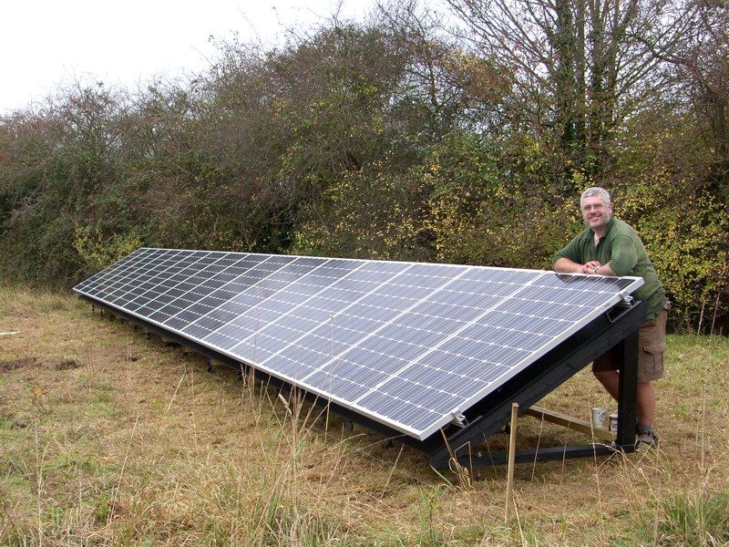 Following my successful
solar PV installation
it is time to firm up plans for the
complimentary wind turbine. While the photovoltaic installation
generates more than enough electricity for our needs throughout the
year it suffered from the known issue of making 5 times as much in the
summer than the winter, thus we still had a shortfall in the winter
despite our winter usage being lower as domestic hot water comes from
the Aga. A small wind turbine 1-2kW should provide the necessary winter
top-up, although I was fully aware of the variability of wind energy –
it varies on a minute-by-minute basis, if not faster and there are long
periods of low output followed by brief excess. In due course battery
storage would be needed, but with both wind and photovoltaic available
the battery reserve capacity could be small.
Following my successful
solar PV installation
it is time to firm up plans for the
complimentary wind turbine. While the photovoltaic installation
generates more than enough electricity for our needs throughout the
year it suffered from the known issue of making 5 times as much in the
summer than the winter, thus we still had a shortfall in the winter
despite our winter usage being lower as domestic hot water comes from
the Aga. A small wind turbine 1-2kW should provide the necessary winter
top-up, although I was fully aware of the variability of wind energy –
it varies on a minute-by-minute basis, if not faster and there are long
periods of low output followed by brief excess. In due course battery
storage would be needed, but with both wind and photovoltaic available
the battery reserve capacity could be small.If I am going to the effort of installing a wind turbine why not do more than just supply our electricity needs? The ideal situation is to have sufficient electricity left over to be able to run a heat pump to make a decent contribution to our house space heating requirements, with this in mind a 10kW turbine would be more appropriate.
Joint venture
 The supplier of my photovoltaic
components was PVfit Ltd and I had mentioned my next plan to MD, Dave
Houston. We soon established that it could be mutually beneficial if we
worked together on a wind turbine project. PVfit wanted to develop
their business as 'GenFit' and include wind turbines as part of their
portfolio. In order to gain MCS (Microgeneration Certification Scheme)
accreditation it is necessary to
complete an installation and have it approved by a certifying body
which includes checking that the design and build confirm to a set of
stringent standards. Clearly it is difficult to put together a complete
package for a customer with all costs evaluated without actually having
already completed the task at least once. As with the photovoltaics I
was keen to do the work myself so that I could fully understand the
subtleties and quirks. This also made it good opportunity to evaluate
the whole process with PVfit gaining accreditation, in exchange I would
get much of the project 'at cost'.
The supplier of my photovoltaic
components was PVfit Ltd and I had mentioned my next plan to MD, Dave
Houston. We soon established that it could be mutually beneficial if we
worked together on a wind turbine project. PVfit wanted to develop
their business as 'GenFit' and include wind turbines as part of their
portfolio. In order to gain MCS (Microgeneration Certification Scheme)
accreditation it is necessary to
complete an installation and have it approved by a certifying body
which includes checking that the design and build confirm to a set of
stringent standards. Clearly it is difficult to put together a complete
package for a customer with all costs evaluated without actually having
already completed the task at least once. As with the photovoltaics I
was keen to do the work myself so that I could fully understand the
subtleties and quirks. This also made it good opportunity to evaluate
the whole process with PVfit gaining accreditation, in exchange I would
get much of the project 'at cost'.Just to add a slight confusion to this write-up, my friend Dave Bowyer is mentioned a few times, he is a chartered mechanical engineer who works in the oil industry and his help has been invaluable. Whenever 'Dave' is mention it is him and I'll address PVfit's MD as 'Dave Houston', his mugshot is opposite.
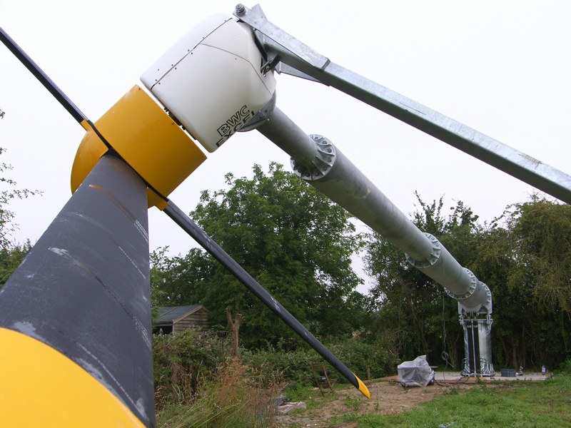
Turbine selection
Our house is situated at the edge of a village and we have a meadow to the rear. Placing the turbine in the far corner still meant that it would be closer to habitation than many turbines so the noise characteristics would play an important part of the selection criteria. At the time there were only two 10kW MCS accredited turbines which seemed quiet enough to meet the requirements. The Aircon10S and the Bergey Excel 10kW. While the Aircon looked on paper to be a superb machine there was still that niggling doubt that it was a new machine and quite complicated; how would maintenance turn out in 10 years time? On the other hand the Bergey had a robust simplicity and a 30-year track record. The decision was not decided yet though: the Aircon had a better yield and was much quieter, but the Bergey did meet the required noise specification and was more like a 'Land Rover in the sky' which had a certain appeal.Maintenance was a crucial consideration and I wanted the ability to be able to do my own repairs if necessary. Climbing a tower to gain access was not a realistic option and using a crane would not always be possible, especially when the ground was wet so a tipping tower was the logical choice. There is a compromise between turbine height and yield - the higher the better - so I looked for the tallest tipping tower available. The Bergey was offered with a 20m hydraulically tipping monopole and the Aircon could be supplied with an 18m hydraulic tipping monopole, so the Bergey gained a slight advantage with the extra height partially compensating for the lower energy yield. The site has a clear view in the prevailing wind direction, but there are some trees and hedgerows which may effect my yield. The 20m tower and the slightly higher ground looked like it was a good option. Dave Houston looked at the MCS guidance documents and evaluated the site against these. The Bergey appeared to conform to all requirements including noise in relation to neighbouring dwellings, to the south-west, so I decided to go with the Bergey on a 20m tipping monopole.
SIAC Wind Energy had an exclusive agreement with Bergey Wind Power to supply turbines in the UK, so the kit of parts would be purchased through them. SIAC supply a kit which comprises of tower (commissioned from Hutchinson Engineering), foundation pack, turbine and inverter. Other components need to be sourced separately, such as the foundation rebar (although I would have thought this was really part of the foundation pack), electrical components, concrete etc.
Usually, the components which allow the tower to tilt (hinge pins, brackets, hydraulic rams, hoses, etc) are not supplied to end users, so I would have to pay extra for these parts.
Planning permission and DNO approval
Despite national policy documents indicating that we should be adopting micro-generation, planning permission requirements vary considerably throughout the country. In some places there is a default acceptance as long as it conforms to MCS design criteria and in others places if you can see the turbine it is rejected! Breckland District Council initially seem to be erring towards the difficult end of the spectrum, nevertheless with the provision of much additional supporting evidence and a very long delay the application was finally approved by officers.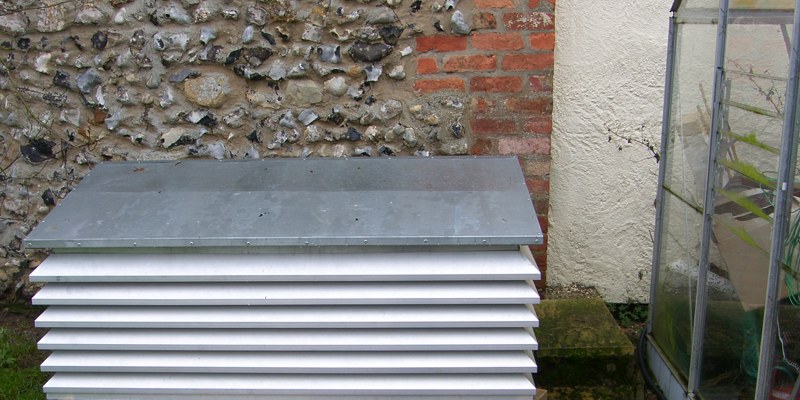
10kW Load dump
Load dump control system
I shouldn't need an upgraded supply, because in reality I want to use the power not to export it, so there must be another option. I could fit a load controller which automatically switches the power for hot water and space heating whenever it is available, keeping the export power within limits. In order to do this with guaranteed effectiveness it was necessary to construct a 10kW load dump resistor bank for those times in the summer when the water was already hot and there was nowhere else for the power to go. Hopefully, there would be little need of the load dump, as it seems such a waste to generate and then burn the power.
After discussion with my local DNO engineering office and a technical explanation of how I would achieve the power control it was agreed that as long as I limited the export power to 5kW total (that includes the PVs) I could proceed. I suspect this power limit requirement would be a show-stopper in many cases as the extra cost of the control equipment was going to add a few thousand pounds to the project cost, but it is cheaper than a supply upgrade.
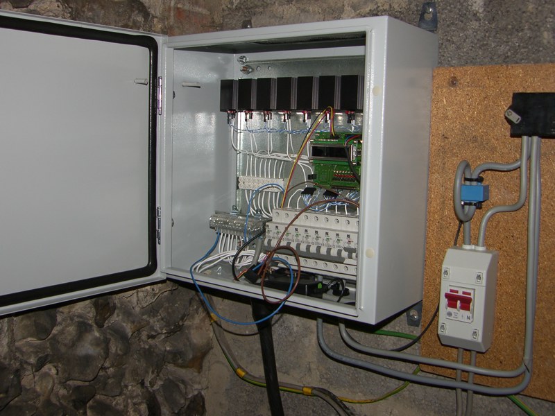
Out of chronological order, picture above is the load dump (eight 1.5kW, 47ohm resistors) housed in its custom louver box next to our greenhouse. Adjacent is the control system during development. The system can quite happily dissipate 10kW continuously, that is equivalent to 3 electric ovens and is sufficient to ensure I don't export more than 5kW. It should be noted this is a last resort protection mechanism, the objective is to never need to dump power. I have some ideas for how to use excesses in the summer to do useful things, but that will be a future article.
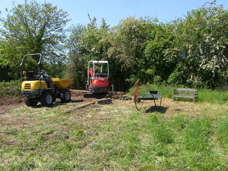
Hired mini-digger and dumper
Finished hole
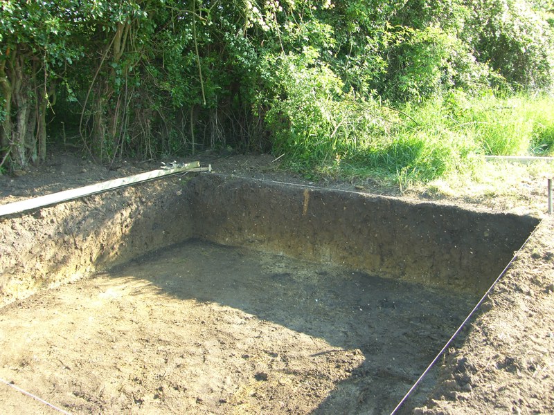
Start work on site
With official planning permission granted for a Bergey Excel turbine on a 20m tower, the real work can start.A mini digger and dumper were hired from Dereham Hire
 for the weekend. Saturday morning was spent clearing
the site and marking out the hole. The corner of our meadow was clearly
marked by a thorn bush, complete with historic barbed wire;
nevertheless I checked with our neighbour in case there were any
discrepancies. In the distant past there was a ditch around the meadow,
but over time this has filled itself in but there was still a
depression meaning that the site sloped slightly. This would mean the
foundation shuttering would need a little more care, but on the plus
side there was ample opportunity to spread the muck from the hole.
Digging started on Sunday morning with my son operating the dumper; the
small equipment meant it took most of the day but by sunset the hole
was more-or-less done.
for the weekend. Saturday morning was spent clearing
the site and marking out the hole. The corner of our meadow was clearly
marked by a thorn bush, complete with historic barbed wire;
nevertheless I checked with our neighbour in case there were any
discrepancies. In the distant past there was a ditch around the meadow,
but over time this has filled itself in but there was still a
depression meaning that the site sloped slightly. This would mean the
foundation shuttering would need a little more care, but on the plus
side there was ample opportunity to spread the muck from the hole.
Digging started on Sunday morning with my son operating the dumper; the
small equipment meant it took most of the day but by sunset the hole
was more-or-less done.The year 2012 started with a drought and hosepipe ban, but then the rain came and my hole started to look a bit like a swimming pool, OK an exaggeration but the clay soil did tend to puddle and there could be an inch or two of water in the bottom which was reluctant to drain away. I intended to build the steel reinforcing cage and foundation pack in situ, which required a firm footing and the heavy clay meant that the bottom was likely to become sticky. A visit to my local quarry and a trailer load of stones ensured that work could continue without risking a quagmire.
Delivery of foundation pack and tower
To minimise delivery costs the foundation pack and tower were delivered together, I would collect the turbine head later. Rather disconcertingly there was no option for delivery using a HIAB, so off-loading was my responsibility. I borrowed a fork truck from a friend in Hingham and had already spoken to a neighbour in the village with a Wiesmann loader in case of problems – which was a good job because I got the fork truck stuck in the stones of our drive and needed help for the last couple of parts.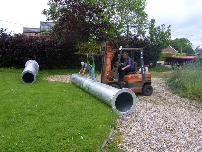

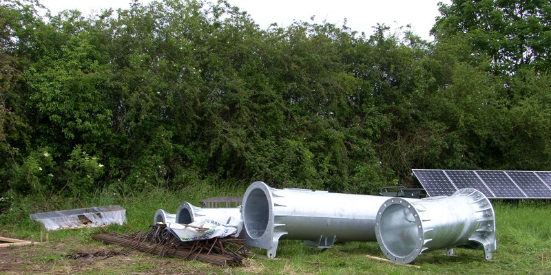 The foundation pack only included
16 high tensile studs, three spacer rings and braces for the hydraulic
ram mounting pad, the rebar had to be purchased separately. In terms of
value-for-money, the foundation pack is pretty poor. Interestingly,
SIAC did not recommend a rebar supplier and were quite interested to
know who we used and how much it cost. The rebar was supplied by
Hy-Ten, generally fine but as you will see later there was a minor
niggle with some of the bending.
The foundation pack only included
16 high tensile studs, three spacer rings and braces for the hydraulic
ram mounting pad, the rebar had to be purchased separately. In terms of
value-for-money, the foundation pack is pretty poor. Interestingly,
SIAC did not recommend a rebar supplier and were quite interested to
know who we used and how much it cost. The rebar was supplied by
Hy-Ten, generally fine but as you will see later there was a minor
niggle with some of the bending.Isn't it odd how the perception of size changes? When an articulated lorry turned up in the village with the tower components parts, it looked so big, but when off-loaded in the meadow they appear much more manageable. Considering its size and apparent sturdy construction the tower is actually rather a light weight at not much over 3-tonnes. Credit to the delivery company as the driver was very helpful.
Construct Foundation
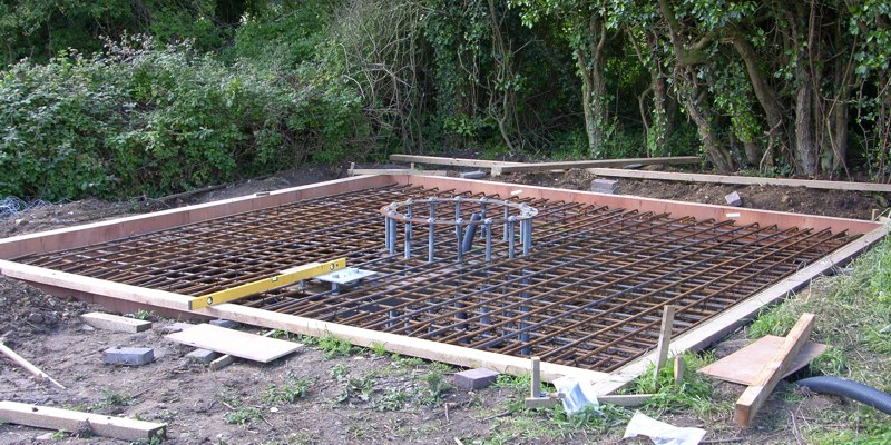 I built the shuttering fairly
accurately to size, reinforced with 4x2 timber to keep it square. If I
did the job again it may be easier to increase the clearance by
50-100mm. Usually the rebar is held together with wire ties applied
with a rebar tying tool, but I used cable ties; be warned there are a
lot to do and it results in very sore fingers.
I built the shuttering fairly
accurately to size, reinforced with 4x2 timber to keep it square. If I
did the job again it may be easier to increase the clearance by
50-100mm. Usually the rebar is held together with wire ties applied
with a rebar tying tool, but I used cable ties; be warned there are a
lot to do and it results in very sore fingers.Dave Houston had been working on finding components, sorting costs, arranging suppliers and working up the extensive paperwork required but he joined me to help with the cage assembly.
Use larger breaking strain ties as there is over a tonne of steel in the cage. Start by assembling the foundation kit in situ, I added three adjustable feet to help get the centre section levelled up, then make the base mesh, fit the double-bend side pieces and belt; finally build the top mesh. You can see the small issue we had with some of the rebar side pieces ... although the 90° bends are accurate they didn't necessarily line up with each other in the same plane, so tying it in to the bottom grid meant it didn't align to the top grid. This shouldn't really affect anything other than making the cage assembly more difficult. The rebar delivery included a fair number of extras so the worst examples were discarded.
Concrete delivery with MOLI pump just visible behind

Base filled!
 The pad requires a high strength FND2 Class II concrete, somewhat
more expensive than your normal grade due to the higher levels of
cement in the mix.
TBL Concrete Ltd have a
distribution facility only 5 miles away and a representative was happy
to come and see my site, quote to supply and provide a mix certificate
to demonstrate its properties. My site has good access when dry but
there is little chance of getting laden mixer trucks across the meadow
when the ground is wet. Moving 50-tonnes of concrete is not a trivial
task so getting the trucks within pouring distance needed careful
consideration. TBL kindly offered to try an empty truck to help
evaluate ground conditions, but I was beginning to think a more
reliable solution should be found especially with the continuing rain.
A couple of dumpers would probably do the job, but then I came across
MK Bedford and their low pressure MOLI pump, more expensive than
dumpers but so much easier.
The pad requires a high strength FND2 Class II concrete, somewhat
more expensive than your normal grade due to the higher levels of
cement in the mix.
TBL Concrete Ltd have a
distribution facility only 5 miles away and a representative was happy
to come and see my site, quote to supply and provide a mix certificate
to demonstrate its properties. My site has good access when dry but
there is little chance of getting laden mixer trucks across the meadow
when the ground is wet. Moving 50-tonnes of concrete is not a trivial
task so getting the trucks within pouring distance needed careful
consideration. TBL kindly offered to try an empty truck to help
evaluate ground conditions, but I was beginning to think a more
reliable solution should be found especially with the continuing rain.
A couple of dumpers would probably do the job, but then I came across
MK Bedford and their low pressure MOLI pump, more expensive than
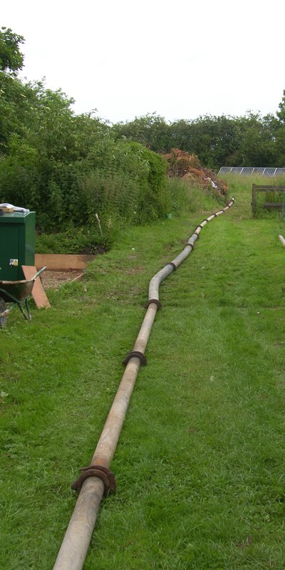
dumpers but so much easier.There were four mixer lorry deliveries during a very warm day. Friends came to help, but the hope was we would be watching the pump do the work. It didn't quite work out as there was a blockage in the pipe during the second load, somewhat stressful for half an hour while we split the pipe to empty the offending 'cement ball'. Nevertheless a neat solution to the concrete moving problem. I said earlier that Dave's help was invaluable and here he is again holding the concrete delivery pipe in picture opposite.
Wait
Now there was a wait for a few weeks while the concrete achieved rated strength, giving me time to get some paying work done.Alternative inverter trial
During this time Dave Houston and I were approached by SIAC to see if I would be interested in trialling a new inverter. SIAC already knew about my electronics background and electric car experience and thought I might be willing to help, which of course I was. I asked for specification and found out it was the Gendrive inverter, a unit I had already looked at while researching this project. SIAC said that although the standard DTI (Diversified Technology, Inc) inverter matched to the Bergey turbine was just fine they were keen to try an alternative so that they had a supply option, apparently the import duty on the DTI unit also made it quite expensive. It later transpired that DTI was due to close their inverter business and the future supply was somewhat uncertain. I believe it has now been taken in-house into the Bergey business in order to secure future supplies.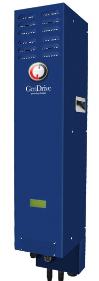
Gendrive inverter,
Company now in liquidation (2014)
As this was a trial, both Gendrive and SIAC wanted to check the inverter performance against wind speed. So an anemometer and wind vane would need to be fitted, but there was some uncertainty as to how to do this. Again I stepped in to assist … I was hoping to fit a camera to the tower and I could fit the anemometer and wind vane to the camera bracket by welding on suitable fittings. It then transpired that the anemometer needed to be 5-6 feet from the tower, whereas the camera bracket was going to be a lot closer and thus smaller. Ah well, I had said I could do it so I ordered some bigger steel stock and fabricated a suitable bracket. This was then galvanised by BMT
in Yarmouth just in
time for the final assembly. Unfortunately my camera didn't arrive in
time, so that would have to go on later.Bat survey
One of the conditions of my planning permission was that I did a bat survey for 10 nights in June and based on this if necessary I agreed to turn off the turbine in the summer evenings during the bat feeding time. The weather was less than ideal for bats early in the month so I waited, but by the middle of the month I needed to get on with the survey as the permission was quite specific that it must be done in June. I acquired the necessary kit and duly recorded the bat activity, collecting nearly 30Gb of data.There are pipistrelle bats and maybe brown long-eared bats nearby, and I enjoy watching them in the summer. I was aware of their usual flight patterns which was not usually around the turbine site. The survey demonstrated that there was very little activity apart from a couple of nearby fly-pasts, but no significant activity. Normally bats follow linear features such as hedge lines, but our hedges vary hugely in width and height so are not classical linear features.
Collecting turbine head
 It was quite expensive to have the
turbine head and rams delivered, so much so that it would be more
economic for me to pick them up. I had planned to collect them a week
or so prior to the final build, but for some reason there was a delay
in getting them ready for collection. At the time I simply though it
was because I was collecting rather than having them delivered, but it
was a bit odd, because I had paid a deposit for the kit which should
have been reserved and waiting for me.
It was quite expensive to have the
turbine head and rams delivered, so much so that it would be more
economic for me to pick them up. I had planned to collect them a week
or so prior to the final build, but for some reason there was a delay
in getting them ready for collection. At the time I simply though it
was because I was collecting rather than having them delivered, but it
was a bit odd, because I had paid a deposit for the kit which should
have been reserved and waiting for me.A couple of days before the final assembly I borrowed Dave's plant transport trailer. I set off to Cheltenham to fetch the turbine head, rams and on the way back I would call in at Cambridge to pick-up the trial Gendrive inverter.
I wasn't expecting it to be yellow, but that is definitely a bright yellow tail in the box. I thought I was getting the less obvious grey but I could always spray it later. I don't mind the yellow, but others might and it is a fairly dominant feature of the local landscape.
Telehandler
In order to assemble the parts on the day I would need some mechanical assistance. Given long enough I'm sure we could have done it with a timber A-frames and the Land Rover winch, but this was not the time to play those games. Another local company provided the solution, GB Plant Hire near Norwich could drop
off and collect a JCB 520, one of the smallest telehanders in the JCB
range. Just right for me as I had not used one before and as it turned
out perfect for the job, just enough capacity yet nimble and easy to
use.Assemble parts !
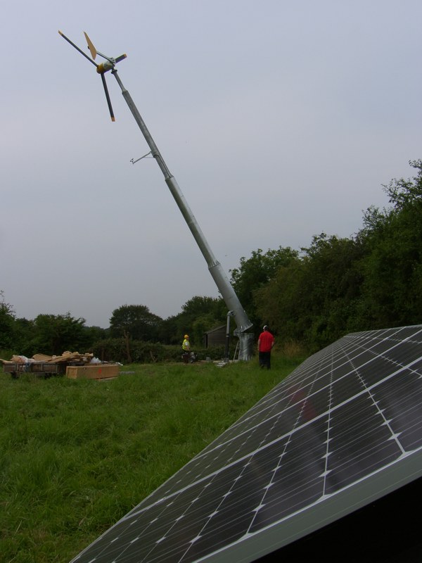
With all the components and equipment on site it was time to assemble. SIAC had offered to overview our efforts on site. Although there were a fair number of 15m towers already installed, it transpired that the 20m tower was very new and only two other had already gone up with another one in progress. I also learned why there had been the delay in availability of my turbine … it needed a different 'high-voltage' winding to work with the Gendrive inverter. This was a little disconcerting as my agreement to trail the new inverter was easy to justify because if it didn't work we could swap it back for the original DTI inverter, but that fall-back position was now not so easily available. Too late to worry now and I expected this to work fine because the Gendrive inverter was already in use with other turbines.
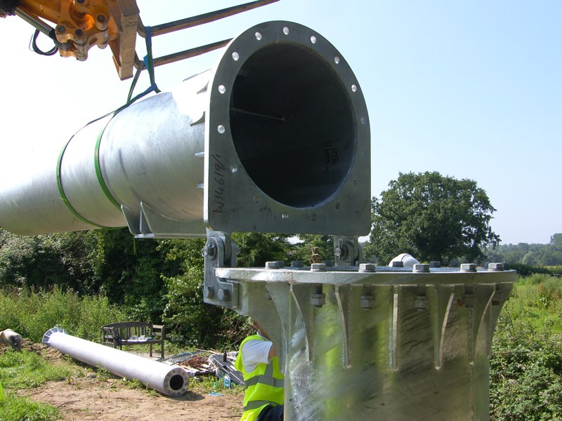
Fit hinge pins and hold section 1 in place
Fit base and torque nuts
Section 2, with Dave torquing bolts
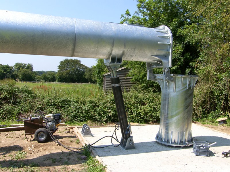
Section 1 supported on rams
Fit head, blades and tail

Test lift, without turbine head, just before tower bounce
L-to-R: Dave Houston, I'm operating the hydraulic pump, Samuel (my son) bringing tea
Final lift
As we now know the tower (built exclusively for SIAC by Hutchinson Engineering in Widnes) was little more than a prototype and there were some teething problems:
- There was some discrepancy over the type of nuts and the placement of the fixed tower base. The on-site SIAC engineer decided to swap the supplied half nuts for full nuts, but this meant the space between the concrete base and the tower increased, which turned out to be too high for the rams to fully reach.
- My rams didn't fit into the base bracket because welded ends made them too wide. To avoid delay we used the SIAC rams and I would grind down the welds of my rams later.
- Weld distortion is a known consideration with large fabricated structures. This particular tower suffered quite a bit which meant levelling the base nuts a waste of time, because only a few of them actually touched the metal. The nuts which didn't touch the flange were spun up until they touched, which aggravated the height issue above.
- Weld distortion resulted in large flange gaps, which in some cases could not be fully closed even when the fixings were at full torque.
- The increased base height necessitated using the upper pin on the ram bracket in order to allow the rams to reach. This meant in the tipped position the tower top was much further off the ground than planned, so subsequent work involved extended ladders.
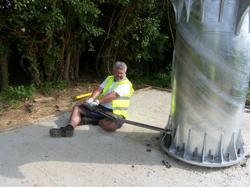
The tower flexed a fair bit due to its own weight when horizontal and light could be seen through the flanges between section 2 and 3 despite the bolts being at full torque. Using the telehandler to bend the tower upwards, thus more than compensating for its own weight enabled the bolts to be given at least an extra half a turn, which then closed the flange gap. The situation was exacerbated by weld distortion mentioned above, but it raises the question as to what torque the bolts are really subjected to in service?
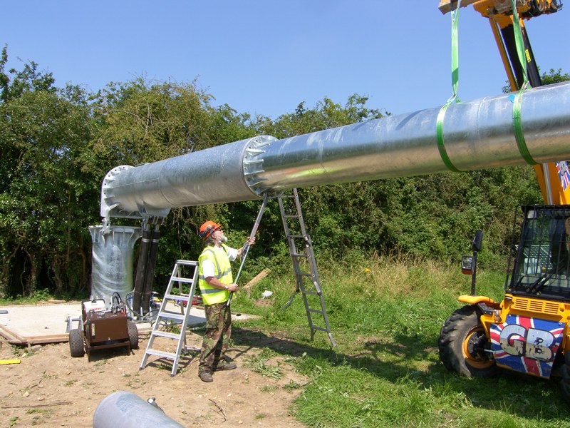
Most worrying was the amount of tower bounce during lifting. We thought the rams may have air in them so purged them again, although this improved the situation there was still a staggering amount of flexing, easily over 500mm of bounce at the end and a dramatic flexing of the hinge pins and associated 40mm thick steel brackets, it certainly gave the welds a decent workout. To alleviate the bounce it was necessary to raise the tower a little at a time allowing the oscillation to die down between increments. The oscillation didn't happen consistently, it could start at any angle but if it did the result was bad and it got out-of-hand quickly, other times the tower would go up almost all the way before any hint of wobble.
Fitting the Gendrive inverter
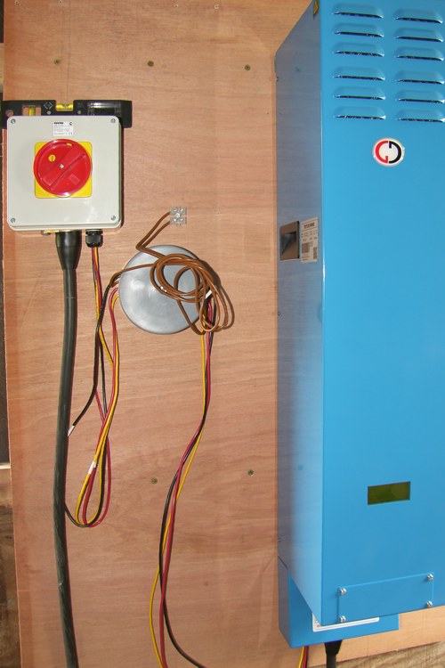 Gendrive arrive on-site to set-up their inverter with its new
parameters theoretically duplicating the DTI
power map. It turns out that although there is just sufficient
room in my new kiosk to fit the inverter, there would not be enough
space to take the covers off. This is an evaluation unit and I don't
want to make life difficult so the location of the inverter is moved to
an adjacent outhouse. I can make some brackets later to allow the whole
kiosk to be removed and the inverter could then go into its intended
home. Picture shows a surprise addition, a common-mode choke (round
object), that will need a proper home and decent wiring connections.
Gendrive arrive on-site to set-up their inverter with its new
parameters theoretically duplicating the DTI
power map. It turns out that although there is just sufficient
room in my new kiosk to fit the inverter, there would not be enough
space to take the covers off. This is an evaluation unit and I don't
want to make life difficult so the location of the inverter is moved to
an adjacent outhouse. I can make some brackets later to allow the whole
kiosk to be removed and the inverter could then go into its intended
home. Picture shows a surprise addition, a common-mode choke (round
object), that will need a proper home and decent wiring connections.Despite the snags the tower was built and the turbine was ready to go, all we now needed was some wind … and that was in short supply! There was just enough to get the turbine rotating but not fast enough to start generating. We noticed that there was an occasional low level growl from the turbine at low rotational speed, hopefully that would be sorted out when the inverter was on-line. We checked the brake (electrically shorting the winding) which worked fine bring the turbine to a stop quickly while making a large growl from the tower when it was activated.
It is the end of July and all seems ready to go, but for some reason the inverter does not seem to want to start. I contact Gendrive (copy to SIAC) to discuss the problem. We decide to check the set-up parameters and receive a copy of all programmable parameters to upload to the inverter. With my previous electronics experience Gendrive had already said they were happy for me to established data communication with their inverter and it was no trouble to upload the set-up files. It didn't help, so I started to take voltage and current measurements, which quickly established that a phase was missing – doh! It was a simple error and very easily fixed, nevertheless I would have thought the Gendrive would have reported the missing-phase error and it is not an uncommon event, could be a single blown input fuse or as in this case a bad isolation switch. I understand Gendrive are now looking at better diagnostic reporting of issues like this, so that is a positive outcome.
The system now generates, the light wind aero-noise was barely audible but there is some tower resonance which is already becoming a nuisance.
One thing worth bearing in mind for anyone wishing to use the Gendrive inverter is the whistling noise while it is running. It uses tough IGBT power devices which switch at around 10kHz and so produce an annoying whistle. It is not too loud in an outhouse but could not be used in a habitable space.
At this point I should be packing up my tools and enjoying self generated electricity. However, there is already a hint that things are not right with an annoying resonance from the tower. Read how badly things develop in PART 2
Slightly out of chronological order, but this part really belongs in part 1:
A few weeks after the build was completed Dave Houston had a detailed NAPIT
'on site' inspection of this first build and achieved full MCS
accreditation. There were a couple of minor paperwork discrepancies
which were fixed there and then, which considering the huge amount of
documentation and regulations seems a very good outcome.I perhaps should note that the inspector was not happy with the wiring of the common mode choke mentioned above, but we explained the situation was temporary while Gendrive were sorting the inverter and noise problems; I had the conduit to hand to show it would be fixed. In addition the wind was light but the tower was still making a low level resonant noise, we did not volunteer the problems at higher speeds, but it was noted that it wouldn't be acceptable without the road noise which could also be heard that day. This was confirmation that the noise was not emitted by other turbines.
